I continue to be curious about this "width" stuff and I think I'd enjoy learning what the person who programmed intended it to do.
In the abscence of that sort of info I went ahead and made a track bounce using Channel Tools with "width" widgets spread to the sides. The "L" was set at -15 degrees and its width was 50%. The "R" was set at +15 degrees and its width was also 50%.
As a comparison but certainly not a direct comparison I also made a bounce to track of the same source running through Waves S-1 with its "width" parameter set to "2"
Here is a screen shot:
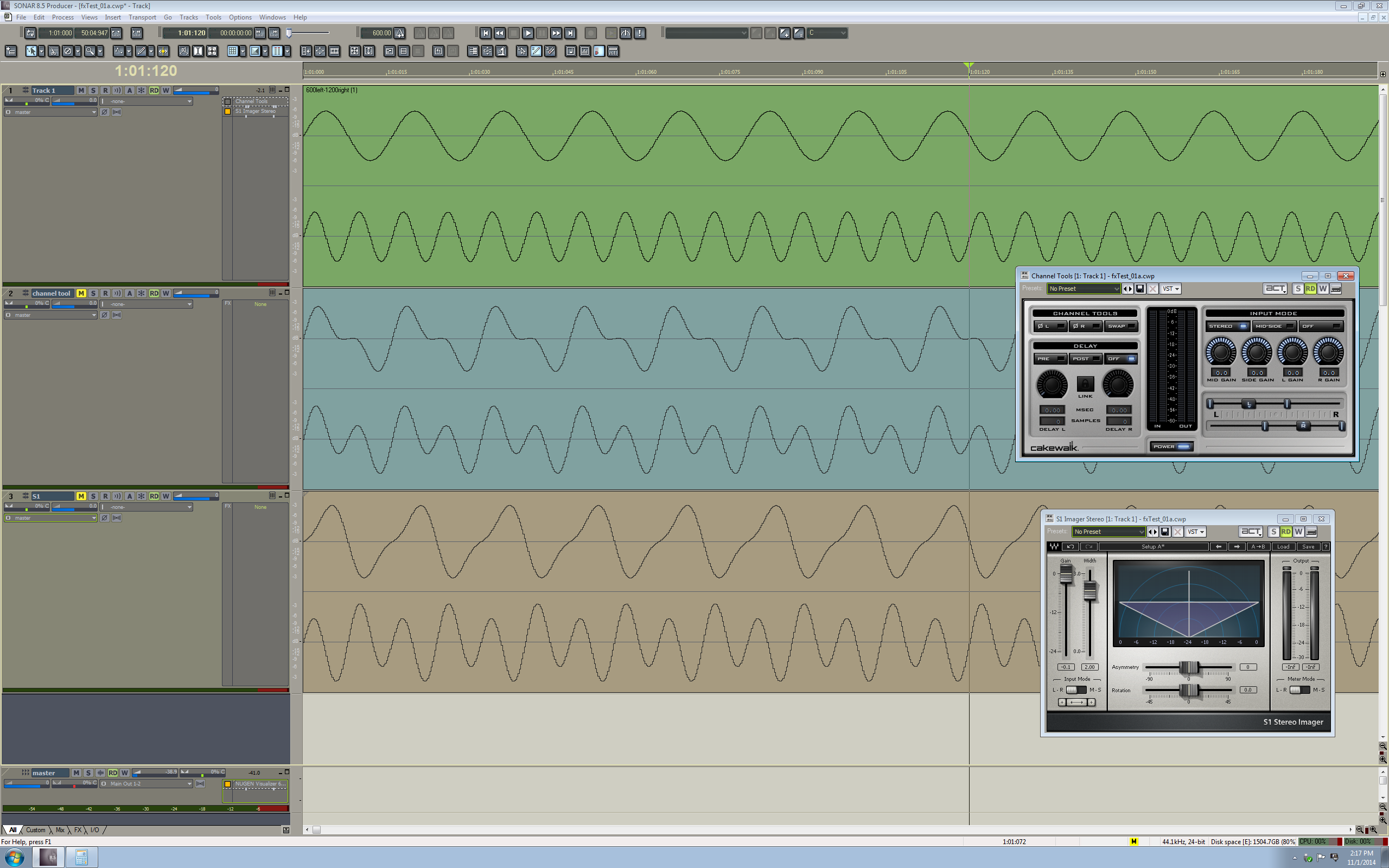
I suggest using a right click view image to see it at full scale
The change in the waveforms makes me very curious about what happens in either of the "width" processes. I don't know how to interpret the shapes I am seeing so I want to share it as it seems like some sort of specific result and maybe someone can share some ideas with us.
I found it interesting that increasing the "width" of channel tools made my level meters indicate an increase in output while increasing the "width" in Waves S-1 made my level meters indicate a decrease in output levels, although neither of the bounced tracks seem to clearly illustrate the difference I saw on the master bus level meters when I played the source track with one or the other dsp set as active.