2:43AM
Max Output Level: -68 dBFS

- Total Posts : 1147
- Joined: 2013/06/24 07:59:49
- Location: PHX
- Status: offline

Shade Tree Repair Guide: Replacing Waldorf Q LCD
Learn How to Swap Out the LCD Panel in Your Waldorf Q Kb or Q Rack! Preface: I am a proud owner of a version-2 Waldorf Q rack. I bought it pretty much brand new and unused from a local Craigslister a couple of years ago. The LCD, however, had a strange problem. The bottom portion of the LCD was either damaged or was decomposing. As you can see in the following pictures, some of the LCD text does not display because of this issue. 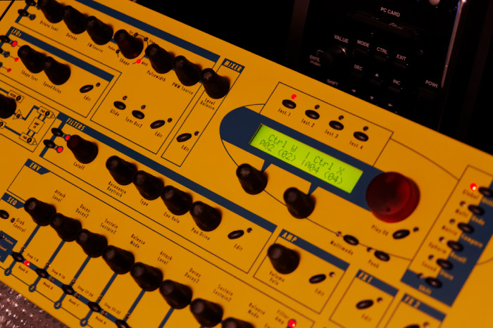 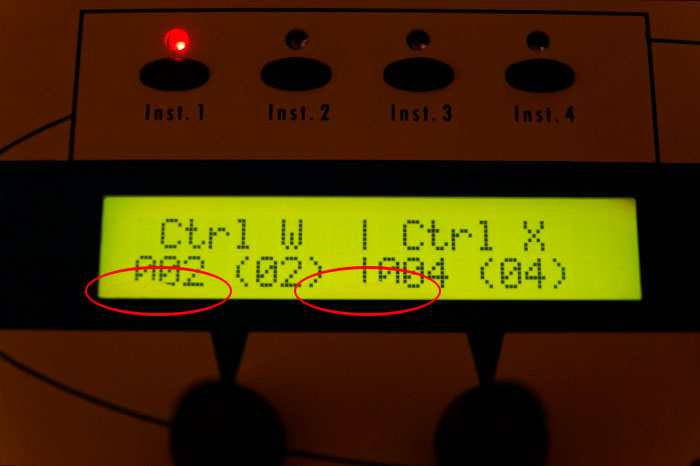 So in order to get the Q back up to good cosmetic condition, I decided to replace the LCD. However, I wanted to change the LCD to a better-contrast, "negative" display...and blue! Overall, the process of LCD replacement is not documented very well in other parts of the Internet. There are a few threads/webpages associated with a swap-out, but none that I could find with any good level of detail. So here is my contribution to the Internet, and the Q owners/tweakers. So let's get down to business! Disclaimer: This how-to requires a good level of skill, discipline, and patience. For some, even cracking open a vintage synth is daunting and may cause uncontrolled shaking and nausea. Proceed with caution and at your own risk! Background the Various Q LCD Screens: Before we begin, let's examine a list of the various Waldorf "Q" derivatives and their LCD screens: • Waldorf Q, v1 (Yellow) -- black on yellow-green positive type• Waldorf Q, v1 (Wave Blue) -- black on yellow-green positive type• Waldorf Q, v1 (Halloween) -- black on yellow-green positive type• Waldorf Q, v2 (Yellow) -- black on yellow-green positive type• Waldorf Q, v2 (Blue) -- black on white (although appearance is rather gray) positive type• Waldorf Q+ (Red) -- black on white (although appearance is rather gray) positive type• Waldorf Q+ Phoenix (Black) -- white on blue negative type As far as I could determine from pictures on the Internet, all versions of the Q (and Micro Q), except for the Phoenix Edition, have positive type character displays, which are the "standard issue" display used in almost everything. The blue versions of the Q and Micro Q utilized a grayish-bluish, positive-type display which is low in contrast, and in my opinion, hard to read. It wasn't until Waldorf made the Phoenix Edition that the LCD screen was finally enhanced to something completely different. The Phoenix version came out in 2007, so perhaps the LCD technology was not available at the time of the first and subsequent issues of the Q and Micro Q (1999-2002). So that settled it; the white on blue negative type was the one I was going to get! It's easy to read and looks awesome, even on a yellow version of the Q. How-To:• Skill level: moderate to difficult• Tools Required: Philips screwdriver, 5.5mm nut-driver or socket, adjustable pliers, precision snips, soldering iron ≥40W, 63/37 solder (the good stuff) or lead-free solder• Components Required for This Particular Repair:--- 2x20 LCD character module (your choice); the one I chose is made by East Rising, ERM2002-1, FSTN-LCD Negative. It was bought on eBay, direct from China (http://stores.ebay.com/buydisplay?_trksid=p2047675.l2563), and it took about 1-1/2 weeks to arrive.--- 1, IDC cable connector socket, 14-position, 2.54mm pin pitch (part number XG4M-1430) **--- 1, board-to-wire connector, 14-position, 2-row, 2.54mm pin pitch (part number 3040-14-00) **--- 1, short length of 14 conductor, IDC flat cable (typical minimum order length is one foot) ** I recommend buying at least two of each part as the cable-making process is an art form without dedicated tools. If you mess up, the spare parts will come in handy! All parts can be ordered either from Digi-Key or Mouser. I chose Mouser because of the options for flat cable. Total cost of this replacement/upgrade was $10.29, though I did it differently. I did not use the board-to-wire connector because I did not order one beforehand, and I did not want to wait another few days for delivery. Anyone reading this, however, should buy and use the board-to-wire connector. What's a board-to-wire connector? It's a device permanently attaches a flat cable to the printed circuit board as opposed to a disconnecting type (plug and socket). See below: So in order to get the Q back up to good cosmetic condition, I decided to replace the LCD. However, I wanted to change the LCD to a better-contrast, "negative" display...and blue! Overall, the process of LCD replacement is not documented very well in other parts of the Internet. There are a few threads/webpages associated with a swap-out, but none that I could find with any good level of detail. So here is my contribution to the Internet, and the Q owners/tweakers. So let's get down to business! Disclaimer: This how-to requires a good level of skill, discipline, and patience. For some, even cracking open a vintage synth is daunting and may cause uncontrolled shaking and nausea. Proceed with caution and at your own risk! Background the Various Q LCD Screens: Before we begin, let's examine a list of the various Waldorf "Q" derivatives and their LCD screens: • Waldorf Q, v1 (Yellow) -- black on yellow-green positive type• Waldorf Q, v1 (Wave Blue) -- black on yellow-green positive type• Waldorf Q, v1 (Halloween) -- black on yellow-green positive type• Waldorf Q, v2 (Yellow) -- black on yellow-green positive type• Waldorf Q, v2 (Blue) -- black on white (although appearance is rather gray) positive type• Waldorf Q+ (Red) -- black on white (although appearance is rather gray) positive type• Waldorf Q+ Phoenix (Black) -- white on blue negative type As far as I could determine from pictures on the Internet, all versions of the Q (and Micro Q), except for the Phoenix Edition, have positive type character displays, which are the "standard issue" display used in almost everything. The blue versions of the Q and Micro Q utilized a grayish-bluish, positive-type display which is low in contrast, and in my opinion, hard to read. It wasn't until Waldorf made the Phoenix Edition that the LCD screen was finally enhanced to something completely different. The Phoenix version came out in 2007, so perhaps the LCD technology was not available at the time of the first and subsequent issues of the Q and Micro Q (1999-2002). So that settled it; the white on blue negative type was the one I was going to get! It's easy to read and looks awesome, even on a yellow version of the Q. How-To:• Skill level: moderate to difficult• Tools Required: Philips screwdriver, 5.5mm nut-driver or socket, adjustable pliers, precision snips, soldering iron ≥40W, 63/37 solder (the good stuff) or lead-free solder• Components Required for This Particular Repair:--- 2x20 LCD character module (your choice); the one I chose is made by East Rising, ERM2002-1, FSTN-LCD Negative. It was bought on eBay, direct from China (http://stores.ebay.com/buydisplay?_trksid=p2047675.l2563), and it took about 1-1/2 weeks to arrive.--- 1, IDC cable connector socket, 14-position, 2.54mm pin pitch (part number XG4M-1430) **--- 1, board-to-wire connector, 14-position, 2-row, 2.54mm pin pitch (part number 3040-14-00) **--- 1, short length of 14 conductor, IDC flat cable (typical minimum order length is one foot) ** I recommend buying at least two of each part as the cable-making process is an art form without dedicated tools. If you mess up, the spare parts will come in handy! All parts can be ordered either from Digi-Key or Mouser. I chose Mouser because of the options for flat cable. Total cost of this replacement/upgrade was $10.29, though I did it differently. I did not use the board-to-wire connector because I did not order one beforehand, and I did not want to wait another few days for delivery. Anyone reading this, however, should buy and use the board-to-wire connector. What's a board-to-wire connector? It's a device permanently attaches a flat cable to the printed circuit board as opposed to a disconnecting type (plug and socket). See below: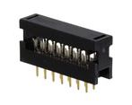 At first, I didn't think I needed it, as I chose to use plugs and sockets instead. However, due to clearance issues, my proposed method did not work. So rather than order more parts and wait, I decided to do my own hard-wiring and just get it done! Steps: (Particular to the Q Rack) At first, I didn't think I needed it, as I chose to use plugs and sockets instead. However, due to clearance issues, my proposed method did not work. So rather than order more parts and wait, I decided to do my own hard-wiring and just get it done! Steps: (Particular to the Q Rack)
1. Lay Q down on semi-hard, padded surface and proceed to remove the 6, phillips pan-head screws on the back and bottom.2. Remove the 6, phillips countersink screws on the sides of the Q.3. Put the Q right side up, and orientate it so the rear faces you. Then lift from the back and flip the top cover away from you, hinging the opening process on the front of the Q. As the cover is lifted and flipped about halfway, a 20-pin connector and ribbon cable will need to be disconnected. Gently pull up on the connector to disconnect the cable from the audio board. 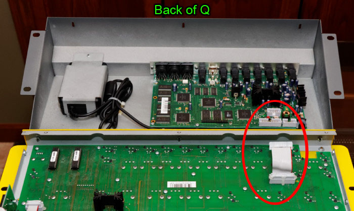 4. The top half of the Q should now be laying flat and upside down. Move the bottom half that contains the power supply and the main audio board to a safe location.5. Locate the LCD screen. Gently unplug the 14-position cable connector. (You may need to use an Exacto or razor blade to cut and remove the hot glue that holds it in place). Then, remove the 4, hex nuts (5.5mm) that surround the LCD board. 4. The top half of the Q should now be laying flat and upside down. Move the bottom half that contains the power supply and the main audio board to a safe location.5. Locate the LCD screen. Gently unplug the 14-position cable connector. (You may need to use an Exacto or razor blade to cut and remove the hot glue that holds it in place). Then, remove the 4, hex nuts (5.5mm) that surround the LCD board.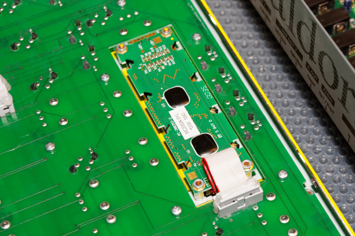 6. Note orientation of the IDC, flat cable. The red wire is used for pin 1, and it is the 0V (ground) connection.7. Lift out the LCD board. Examine it for a bit before saying farewell! Here you can see exactly what is wrong with my particular LCD screen. It looks nasty! 6. Note orientation of the IDC, flat cable. The red wire is used for pin 1, and it is the 0V (ground) connection.7. Lift out the LCD board. Examine it for a bit before saying farewell! Here you can see exactly what is wrong with my particular LCD screen. It looks nasty!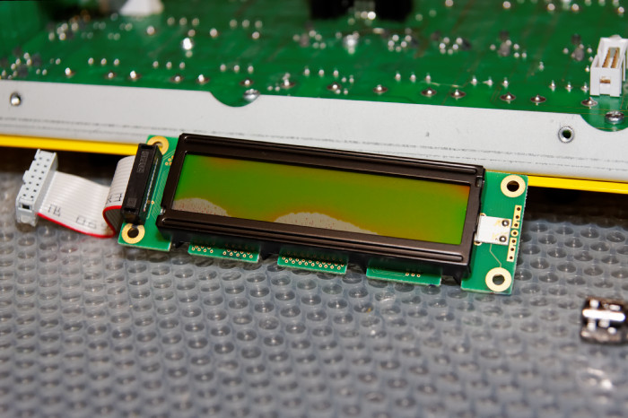 8. Compare the new board vs. old board. Note the position of pin 1. This is important. Also note the orientation ("this side up") arrow on the new board. Also note that the new board has 16 pins while the original board has only 14 pins. The extra two pins (15 and 16) are used for +/- connections for the back light. 8. Compare the new board vs. old board. Note the position of pin 1. This is important. Also note the orientation ("this side up") arrow on the new board. Also note that the new board has 16 pins while the original board has only 14 pins. The extra two pins (15 and 16) are used for +/- connections for the back light.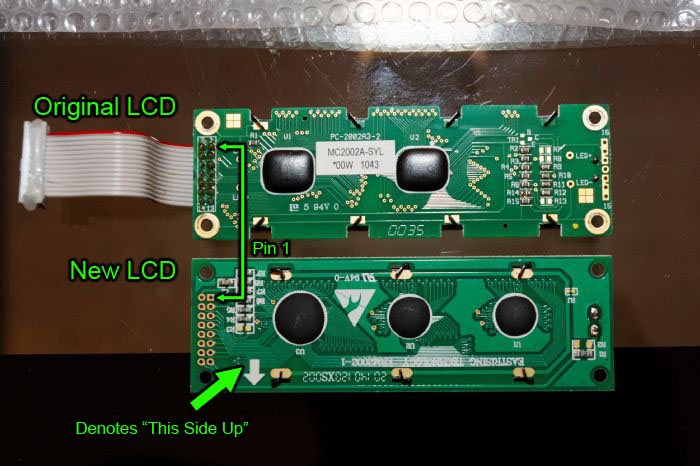 9. Proceed to build your new cable assembly using the following parts: board-to-wire connector, ribbon cable, and the IDC cable connector socket.•• A. Cut, with scissors, the ribbon cable to about 5 inches in length.•• B. If you bought multicolor flat-cable cable like me, then designate the outside, brown wire as pin 1.•• C. With the IDC connector's polarizing tab facing you, insert one end of the flat cable into the IDC connector socket, with the brown wire on the lefthand side. The brown wire will be pin 1, and pin 1 is denoted by the white triangle on the connector. See pic. 9. Proceed to build your new cable assembly using the following parts: board-to-wire connector, ribbon cable, and the IDC cable connector socket.•• A. Cut, with scissors, the ribbon cable to about 5 inches in length.•• B. If you bought multicolor flat-cable cable like me, then designate the outside, brown wire as pin 1.•• C. With the IDC connector's polarizing tab facing you, insert one end of the flat cable into the IDC connector socket, with the brown wire on the lefthand side. The brown wire will be pin 1, and pin 1 is denoted by the white triangle on the connector. See pic.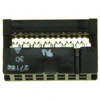 •• D. Make sure the cable is situated perfectly in the piercing teeth. Gently squeeze and hold with fingers so the cable is somewhat gripped by the teeth. •• E. Using the adjustable pliers, set on the wider setting, evenly squeeze the two connector pieces together until the side latches click. Once both are clicked, continue to gently squeeze on various points on the connected to ensure good electrical connection and grip. •• D. Make sure the cable is situated perfectly in the piercing teeth. Gently squeeze and hold with fingers so the cable is somewhat gripped by the teeth. •• E. Using the adjustable pliers, set on the wider setting, evenly squeeze the two connector pieces together until the side latches click. Once both are clicked, continue to gently squeeze on various points on the connected to ensure good electrical connection and grip. 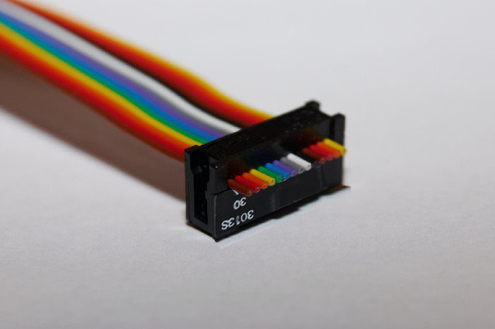 •• F. Using the same process as above, build the opposite end of the cable using the board-to-wire connector. Remember the brown wire/pin 1 arrangement! Pin 1 is the arrow/triangle marker. If unsure, then test fit the board-to-wire connector to the new LCD module with pin 1 of the connector inserted into pad 1 of the board.•• G. Your cable assembly is now complete! Good job! 10. Flux (but do not tin) all the pads on the new, LCD board. NOTE: the vias (holes) are thru-plated so there is no need to solder both sides.11. Insert the wire-to-board connector pins into the LCD board, with the connect being on the component side of the LCD board. Remember, unless you are using an exact LCD replacement board, then there are 16 pads/holes on the new LCD, so ensure your pin 1 on the connector is going into pad 1 on the board!12. Solder pins/pads 1 through 14.13. On the LCD board, flux and tin (small hump of solder) the empty pads 15 and 16.14. Using a small length (about 3 inches) of 2 conductors of the leftover ribbon cable, make a jumper that will connect pad 1 to pad 16, and pad 2 to pad 15. NOTE: Again, this is particular to the LCD module I purchased, your actual board may differ.15. Solder the jumper in place, connecting in parallel, pad 1 to pad 16 and pad 2 to pad 15. See diagram. •• F. Using the same process as above, build the opposite end of the cable using the board-to-wire connector. Remember the brown wire/pin 1 arrangement! Pin 1 is the arrow/triangle marker. If unsure, then test fit the board-to-wire connector to the new LCD module with pin 1 of the connector inserted into pad 1 of the board.•• G. Your cable assembly is now complete! Good job! 10. Flux (but do not tin) all the pads on the new, LCD board. NOTE: the vias (holes) are thru-plated so there is no need to solder both sides.11. Insert the wire-to-board connector pins into the LCD board, with the connect being on the component side of the LCD board. Remember, unless you are using an exact LCD replacement board, then there are 16 pads/holes on the new LCD, so ensure your pin 1 on the connector is going into pad 1 on the board!12. Solder pins/pads 1 through 14.13. On the LCD board, flux and tin (small hump of solder) the empty pads 15 and 16.14. Using a small length (about 3 inches) of 2 conductors of the leftover ribbon cable, make a jumper that will connect pad 1 to pad 16, and pad 2 to pad 15. NOTE: Again, this is particular to the LCD module I purchased, your actual board may differ.15. Solder the jumper in place, connecting in parallel, pad 1 to pad 16 and pad 2 to pad 15. See diagram. 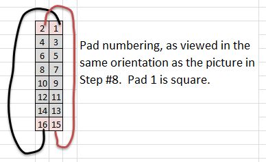 16. Alternative wiring method (what I did): Yours will look nicer since you'll use the wire-to-board connector, but I didn't want to wait for more parts, so here is what I did. To save grief, I alternated sides for each wire (i.e. pins 1, 3, 5, etc. on component side of board, and pins 2, 4, 6, etc. on solder side). This makes soldering 1,000x easier than all wires on one side. 16. Alternative wiring method (what I did): Yours will look nicer since you'll use the wire-to-board connector, but I didn't want to wait for more parts, so here is what I did. To save grief, I alternated sides for each wire (i.e. pins 1, 3, 5, etc. on component side of board, and pins 2, 4, 6, etc. on solder side). This makes soldering 1,000x easier than all wires on one side.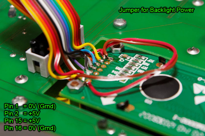 17. The above picture jumps ahead a bit as the board is already mounted and plugged into the socket, but before you do that test, using a continuity checker, any short circuits between pads. Ensure no solder bridges exist!18. If you have a power supply, adjust to +5.0V and connect to pins 1 and 2. The LCD module should light up! 17. The above picture jumps ahead a bit as the board is already mounted and plugged into the socket, but before you do that test, using a continuity checker, any short circuits between pads. Ensure no solder bridges exist!18. If you have a power supply, adjust to +5.0V and connect to pins 1 and 2. The LCD module should light up!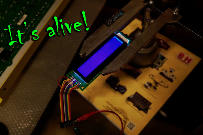 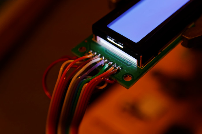 19. Ensure no dust on the plastic lens, and mount and connect the new LCD into the Q. The polarized connector can only go in one direction, i.e. fool proof (refer to picture in Step #16 if needed). 19. Ensure no dust on the plastic lens, and mount and connect the new LCD into the Q. The polarized connector can only go in one direction, i.e. fool proof (refer to picture in Step #16 if needed).
|